Draw Double Line Autocad 2018
ACAD only Frequently, when working on an architectural project, you will first do your schematic layout by using simple lines for walls. Then, as the design requirements begin to take shape, you can start to add more detailed information about the walls, for example, indicating wall materials or locations for insulation. AutoCAD provides multilines (the Multiline command and its equivalent tool on the Draw toolbar) for this purpose. Multilines are double lines that you can use to represent walls. You can also customize multilines to display solid fills, center lines, and additional line types, as shown in Figure 5.25. You can save your custom multilines as Multiline styles, which are in turn saved in special files for easy access from other drawings.

Figure 5.25: Samples of multiline styles
| Warning | The Multiline command is not available in AutoCAD LT 2005. LT does offer the Dline command, which draws simple parallel lines. To use it, enter DL |
| Tip | Multilines are especially useful for metric users who need to draw cavity walls that are usually represented by multiple lines. |
The following exercise shows how you might continue to build information into your drawings by using multilines to indicate wall types:
-
Choose Draw Multiline from the menu bar or type ML
 . You'll see two lines in the prompt area:
 Current settings: Justification = Top, Scale = 1.00, Style = STANDARD Specify start point or [Justification/Scale/STyle]:
Tip The first line in the prompt area gives you the current settings for Multiline.
-
Type S
 (for Scale).
 -
At the Enter mline scale <1.00>: prompt, type 5
 .
. -
Pick a point to start the double line.
-
Continue to select points to draw more double-line segments, or type C
 to close the series of lines.
Let's take a look at the meaning of the multiline settings included in the prompt you saw in steps 1 and 2:
Justification Controls how far off center the double lines are drawn. The default sets the double lines equidistant from the points you pick. By changing the justification value to be greater than or less than 0, you can have AutoCAD draw double lines off center from the pick points.
Scale Lets you set the width of the double line.
Close Closes a sequence of double lines, much as the Line command's Close option does.
Style Lets you select a style for multilines. You can control the number of lines in the multiline, as well as the line types used for each line in the multiline style, by using the Mledit command.
Customizing Multilines
In Chapter 4 you learned how to make a line appear dashed or dotted by using line types. In a similar way, you can control the appearance of multilines by using the Multiline Style dialog box. This dialog box enables you to do the following:
-
Set the number of lines that appear in the multiline
-
Control the color of each multiline
-
Control the line type of each multiline
-
Apply a fill between the outermost lines of a multiline
-
Control whether and how ends of multilines are closed
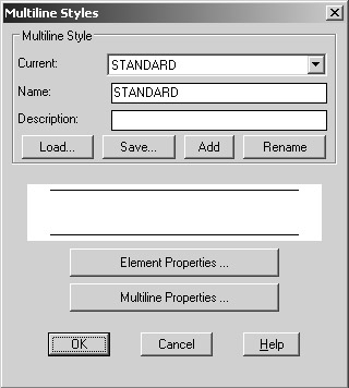
To open the Multiline Styles dialog box, choose Format Multiline Style or type Mlstyle ![]() at the command prompt.
at the command prompt.
| Warning | After you have drawn a multiline in a particular style, you cannot modify the style settings for that style in the Element Properties and Multiline Properties dialog boxes described later in this section. The Multiline Styles dialog box enables you to set up styles only before they are used in a drawing. |
At the top of the Multiline Styles dialog box, a group of buttons and text boxes enable you to select the multiline style you want to work with. The Current drop-down list offers a selection of existing styles. In the Name text box, you can name a new style you are creating or rename an existing style. The Description text box lets you attach a description to a multiline style for easy identification. You use the Add and Save buttons to create and save multiline styles as files so they can be accessed by any AutoCAD drawing. With the Load button, you can retrieve a saved style for use in the current drawing. Rename lets you change the name of a multiline style. (The default style in a new drawing is called Standard.)
In the lower half of the Multiline Styles dialog box are two buttons "Element Properties and Multiline Properties "that enable you to make adjustments to the multiline style currently indicated at the top of the dialog box. This multiline is also previewed in the middle of the dialog box.
Element Properties
Click the Element Properties button to open the Element Properties dialog box, in which you control the properties of the individual elements of a newly created style, including the number of lines that appear in the multiline, their color, and the distance they appear from your pick points. The Element Properties settings are not available for existing multiline styles.
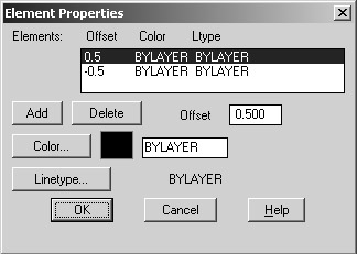
For example, click the Add button to add another line to your multiline. The offset distance of the new line appears in the list box. The default value for new lines is 0.0, which places the line at the center of the standard multiline. To delete a line, highlight its offset value in the list box and click the Delete button. To change the amount of offset, highlight it and enter a new value in the Offset text box.
To change the color and line type of individual lines, use the Color and Linetype buttons, which open the Color and Select Linetype dialog boxes, both of which you have already worked with. Figure 5.26 contains some examples of multilines and their corresponding Element Properties settings.
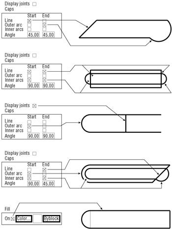
Figure 5.26: Samples of multiline styles you can create
| Tip | You can easily indicate an insulated wall in an architectural drawing by adding a third center line (offset of 0.0) and giving that center line a batting line. This line type draws an S-shaped pattern typically used to represent fiberglass batt insulation in a floor plan. To see how other wall patterns can be created, see Chapter 20. |
Multiline Properties
Click the Multiline Properties button in the Multiline Styles dialog box to open the Multiline Properties dialog box, which lets you control how the multiline is capped at its ends, as well as whether joints are displayed.
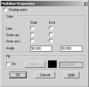
To turn on a cap, click the check box next to the type of cap you want. If you prefer, you can give your multiline style a solid fill by clicking the On check box in the Fill group.
| Tip | You can use a solid-filled multiline wherever you need to fill in a wall with a solid shade (or pouche, to use the drafting term ). You can quickly add a pouche by setting one multiline offset to be 0.0 and the other to be the width of the wall. Then trace either the inside or outside of the wall to be pouched, using the multiline style with the Fill option turned on. |
Joining and Editing Multilines
Multilines are unique in their ability to combine several line types and colors into one entity. For this reason, you need special tools to edit them. AutoCAD provides the Modify menu's Object Multiline option and the command line's Mledit command; both have the sole purpose of enabling you to join multilines in a variety of ways, as demonstrated in Figure 5.27.
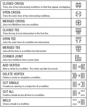
Figure 5.27: The Mledit options and their meanings
Here's how to edit multilines:
-
Type Mledit
 at the command prompt or choose Modify Object Multiline to open the Multiline Edit Tools dialog box (see Figure 5.28), which provides a variety of ways to edit your multilines.
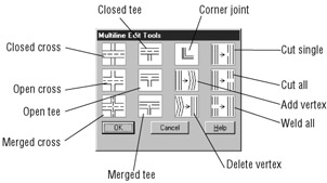
Figure 5.28: The Multiline Edit Tools dialog box -
Click the graphic that best matches the edit you want to perform.
-
Select the multilines you want to join or edit.
Another option is to explode multilines and edit them by using the editing tools you've used in this and previous chapters. When a multiline is exploded, it is reduced to its component lines. Line- type assignments and layers are maintained for each component.
If you are doing a lot of work with multilines, you can open the Modify II toolbar. It contains the Edit Multiline button that opens the Multiline Edit Tools dialog box. To open the Modify II toolbar, right-click any toolbar and then click the Modify II check box in the Toolbars shortcut menu.
Source: https://flylib.com/books/en/4.166.1.52/1/
0 Response to "Draw Double Line Autocad 2018"
Postar um comentário